
Today, Azure IoT Suite provides two end-to-end IoT solutions; Predictive Maintenance and Remote Monitoring. These solutions can be deployed into your Azure subscription and running in just a few minutes, enabling you to get hands-on with all the services that comprise a typical IoT solution. If you have never seen the solutions in IoT Suite, I encourage you to check them out. They will accelerate your learnings on how the plethora of services in Azure can be used to implement an IoT solution that provides telemetry ingestion at massive scale, data storage, analytics, and presentation of data. I lean on these solutions a lot when talking to customers about IoT on Azure as well as the Azure IoT Reference Architecture. And best of all, these solutions are open sourced on GitHub so you can fork them and use them as a starting point to build your own IoT solutions.
In this blog post, I’m going to be using the Remote Monitoring solution to show how you can register a custom device with IoT Hub to send real telemetry (temperature and humidity) data to IoT Hub. I’m not going to go deep into the solution itself. You can do that at your own convenience. This post is all about taking an Azure IoT Starter Kit and connecting it to the solution so you can explore the possibilities of devices in a working solution.
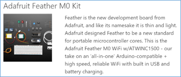
The Microsoft Azure IoT Starter Kits provide a variety of boards, sensors, and controls that you can use to get started with IoT in Azure. The one I’m using for this post is the Adafruit Feather M0 Starter Kit shown here from the Azure IoT Starter Kits page. As you can see, it is packed full of gadgets and can take your mind far beyond the scenario I’ll discuss in this post. BTW, this is not an endorsement of any kind. It is the starter kit that was available to me. If you decide to purchase a kit, explore them all and pick the one that best meets your needs. They are all certified for Azure!
The getting started page for the Adafruit Feather M0 WiFi starter kit is a good place to start and if you are persistent you will find everything you need to be successful. However, one of the reasons I chose to write this blog is to consolidate all the steps into a single document. I spent hours on what I thought would be a rather trivial process and made some mistakes along the way. Also, because the device manufacturer, the IDE, and the Azure platform span different organizations, the documentation tends to be a bit fragmented as you dive deeper into things. So, my goal here is to document a clear and concise path to connecting a custom device to the remote monitoring solution. Specifically, in this post I will show how to
- build a device that can transmit temperature and humidity data to Azure IoT Hub,
- configure the Arduino IDE used to compile and upload code to the device,
- deploy the remote monitoring solution from the Azure IoT Suite,
- register the device in IoT Hub,
- compile and upload the remote monitoring device code to the device,
- observe the telemetry data from the device in the remote monitoring solution.
Build the device
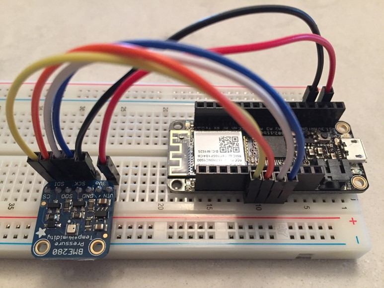
The first step in this process was to build the device to connect to the remote monitoring solution. For this, you need the breadboard, some wires, the BME280 sensor (barometric pressure, temperature, and humidity), and the main Adafruit Feather M0 WiFi module. This was a lot of fun for me personally. The last time I did anything involving a breadboard was back in 19xx when I was in college. It was a rewarding experience back then and a lot of fun xx years later in an internet-of-things (IoT) world. I used this opportunity to expose my youngest son to circuitry and IoT. In fact, he built the device referenced in this section of the post.
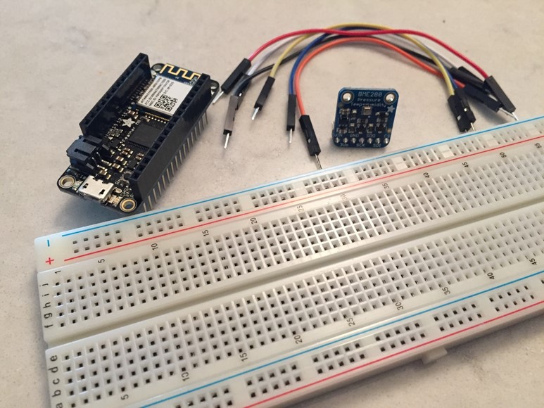
First up, install the Adafruit module and BME280 sensor on the board. Placement on the board is not important. You just need to give yourself some room to work.
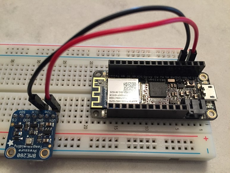
Wire up the power (3Vo) and ground (GND) as shown here.
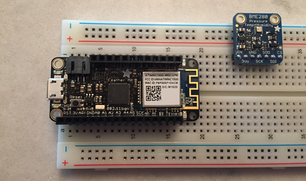
Next, wire up the BME280 sensor. I tried a couple of wiring configurations (I2C and SPI) and eventually settled on the Serial Peripheral Interface (SPI) wiring configuration. What is shown here is the clock (SCK), data out (SDO), data in (SDI), and chip select (CS) from the BME280 connected to pins 13, 12, 11, and 10 on the main module.
Later, we will test this out, but first, we need to setup the development environment so we can program the device.
Setup the Arduino IDE
To program the device, you need the Arduino IDE. Specifically, for the Azure IoT Suite Remote Monitoring Solution, it is advised that you use version 1.6.8 or newer. For this post, I used the Windows version 1.6.9.
Note: I also tested things out on the Mac version and it worked equally as well.
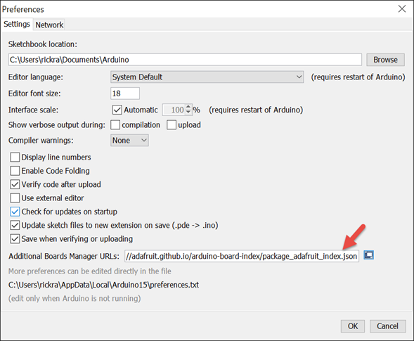
After installing the Arduino IDE, run the IDE and select File -> Preferences. Set the Additional Boards Manager URLS to https://adafruit.github.io/arduino-board-index/package_adafruit_index.json and click OK. This is used by the IDE’s Board Manager to locate new/updated Adafruit boards.
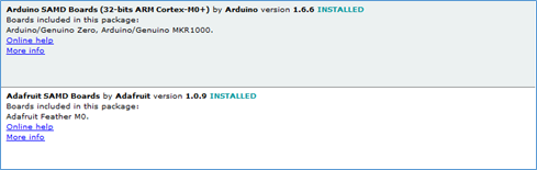
Next, using the Boards Manager, install the Arduino SAMD Boards and Adafruit SAMD Boards as shown here. To open the Boards Manager, select Tools -> Boards Manager.
Close and re-open the Arduino Software IDE.
If you are running on Windows, as I was while writing this post, then you will want to also install the Adafruit Board Drivers. A link to the installer is available here (near the middle of the page). I used the default settings to install the drivers on my machine.
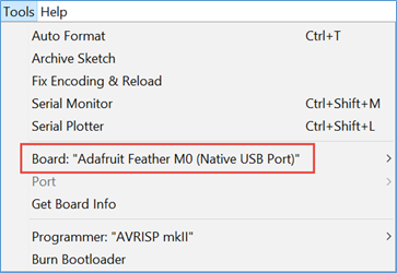
Finally, select Tools -> Board, and then select the Adafruit Feather M0 board as shown here.
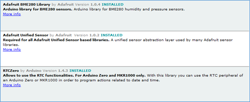
Using the Library Manager, install the Adafruit BME280, Adafruit Unified Sensor, and RTCZero libraries as shown here. To open the Library Manager, select Sketch -> Include Library -> Manage Libraries.
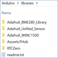
There are two more libraries you need for this solution that you have to download and copy to your Arduino Library folder manually.
- Clone (or download) the Adafruit WINC1500 library.
- Clone (or download) the Azure IoT Hub for Arduino Library.
Copy both libraries to the Documents\Arduino\libraries folder. The Arduino libraries folder now contains the five libraries installed above as shown here.
Test the device
At this stage you are ready to test out some basic functions on the board, such as the blink sample sketch. To do this, plug the device into a USB port and wait about 30 seconds.
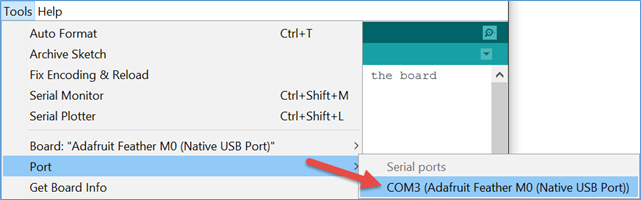
In the Arduino Software IDE, select Tools -> Ports -> [port for the device] as shown here (your COM port may be different).
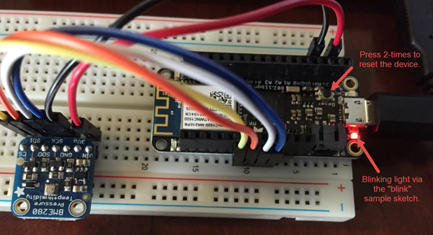
Next, compile (CTRL + R) and then upload (CTRL + U) the blink sketch to the device. After a few seconds the red light on the device will start blinking on/off per the code in the sketch.
Note: The device needs to be reset before you can upload a new sketch to it. To do this, press the reset button 2 times, reconfigure your port setting in the Arduino IDE, and then upload the sketch.
Deploy the Azure IoT Suite Remote Monitoring Solution
To deploy the Remote Monitoring Solution from the Azure IoT Suite, open a browser and navigate to https://azureiotsuite.com. Sign-in using the same credentials you use to sign-in to the Azure portal.
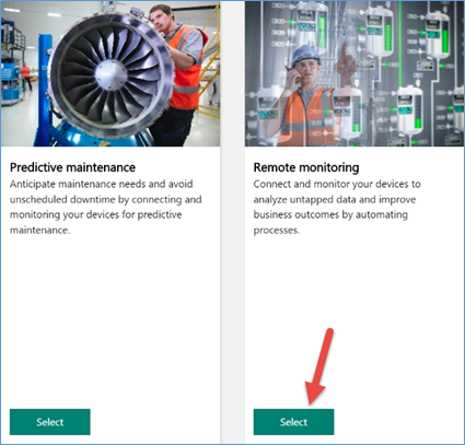
Click the link to Create a new solution.
Select the Remote Monitoring Solution.
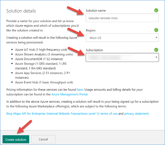
Enter a solution name, select a region, select your subscription you want the solution deployed in, and then click Create Solution.
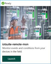
The solution takes about 10 minutes to deploy. After it does, launch the dashboard (ie: web app) for the solution by clicking Launch on the solution as shown here.
Create a custom device Id and key in the remote monitoring solution
The solutions in the Azure IoT Suite uses Azure IoT Hub for bi-directional communication with devices. When you add a device to your IoT Hub, you need to generate a Device ID and Device Key. These are unique to each device and are used by the device to authenticate to IoT Hub before it can send and receive messages.
Note: By having a unique ID and key for each device, you are able to ensure that only devices that have been registered with IoT Hub can authenticate to it. This also enables you to revoke access for an individual device if you ever need to.
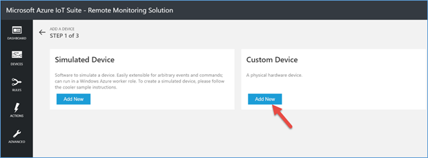
In the dashboard of the Remote Monitoring solution, click the Add a Device button in the lower left corner of the screen.
Next, click the Add New button in the panel labeled Custom Device.
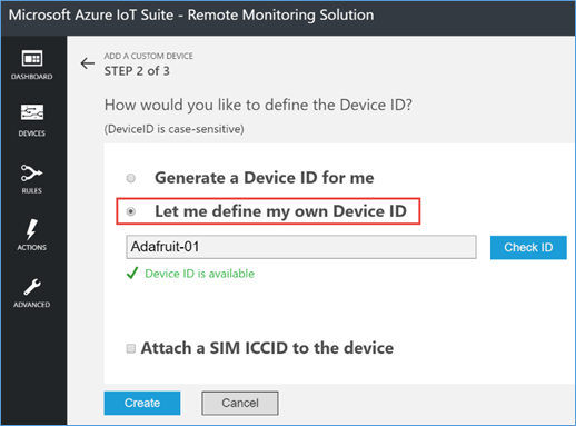
Next, select the option to define your own Device ID. I named my device Adafruit-01. Click the Check ID button to verify the device ID is available in your instance of Azure IoT Hub and then click Create.
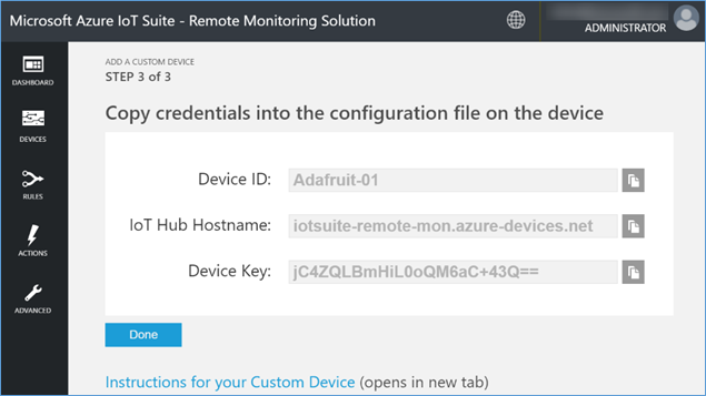
Copy the Device ID, Device Key, and the IoT Hub Hostname to notepad or another text editor so you can retrieve them later.
Upload the remote monitoring sketch to the device
In this section, we will configure the remote monitoring solution code to use the SPI wiring configuration for the device and provide it the Device ID and Key it will need to authenticate to IoT Hub.
Clone (or download) the device code from GitHub or clone (or download) my forked copy that has these changes already applied.
Open the .\remote_monitoring\remote_monitoring.ino sketch using the Arduino IDE.
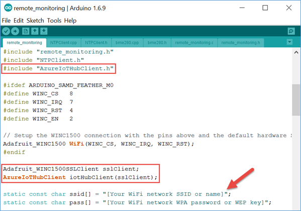
In the remote_monitoring.ino file, include the AzureIoTHubClient.h and initialize an instance of AzureIoTHubClient. Also, set the SSID and Secret for the WIFI network you want the device to use.
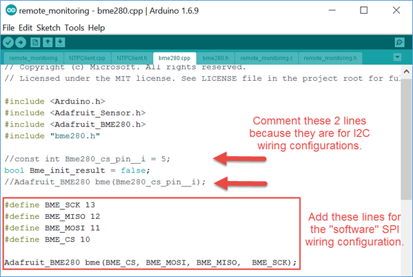
In the bme280.cpp file, change the code to initialize the BME280 sensor using the SPI wiring configuration. The original code assumed the I2C wiring configuration for the device.
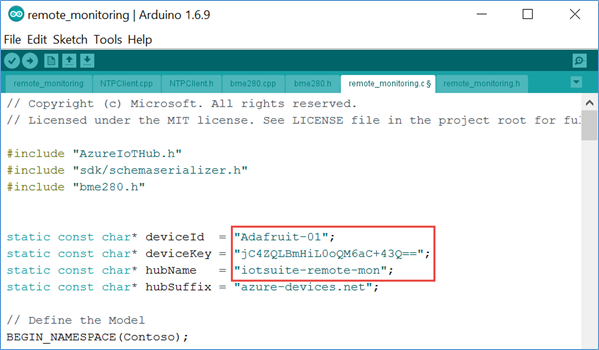
In the remote_monitoring.c file, add the Device ID, Device Key and IoT Hub Name that was created previously.
It’s time to compile this thing and try it out! Press Ctrl-U to compile and upload the sketch to the device.
Note: You will have to reset the device (see above) and subsequently the port in the Arduino IDE before uploading the sketch to the device.
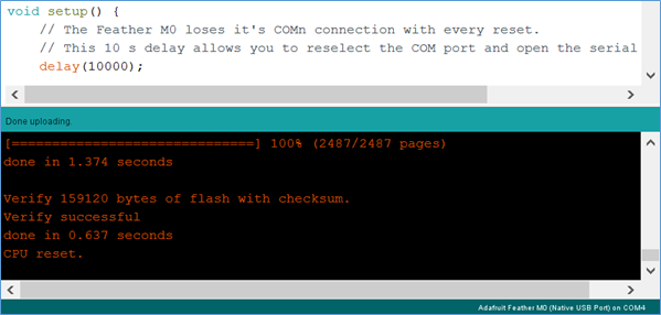
A successful build and upload to the device will result in output similar to what is shown here in the output window of the Arduino IDE.
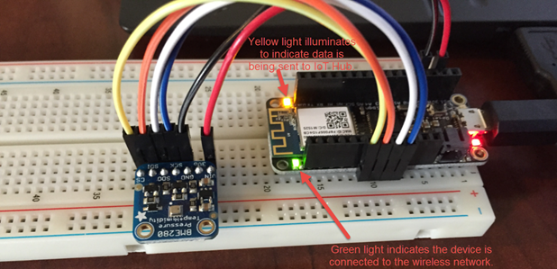
After about 20-30 seconds the device will connect to the WiFi network, initialize the BME280 censor, and then start transmitting data to your IoT Hub instance.
Observe telemetry data sent to IoT Hub
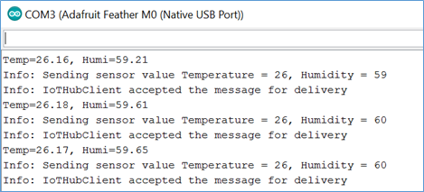
In the Arduino IDE, you can monitor the recordings from the device using the Serial Monitor as shown here. To open the Serial Monitor, select Tools -> Serial Monitor.
Note: It is not necessary at this point to have the device connected to the USB port on your computer. As long as you can provide a power source and be in range of your WiFi network, the device can be placed anywhere and the telemetry data can be observed in the dashboard of the remote monitoring solution.
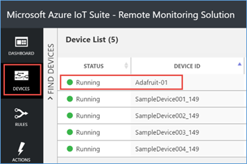
In the Devices page of the remote monitoring solution, the status of the custom device will be set to Running as shown here.
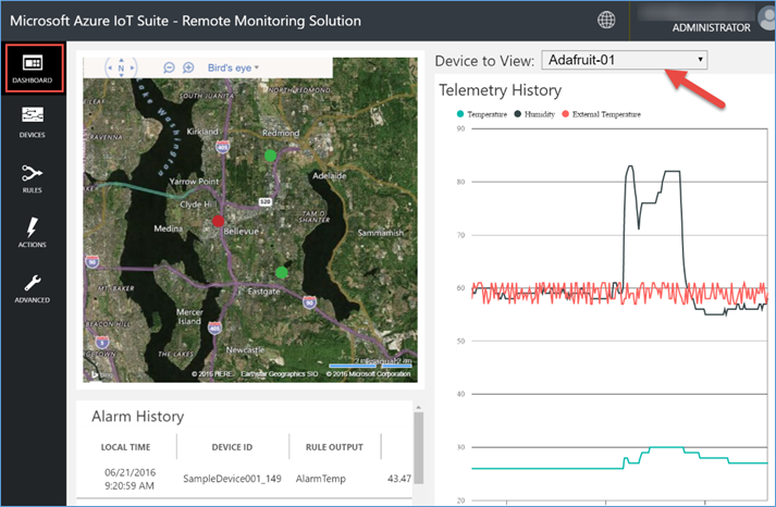
Go back to the Dashboard page and change the device to view setting to the custom device ID to see the telemetry data coming from the device. In the image below, I exhaled on the BME280 device and then touched it with my finger to change the temperature and humidity readings.
Summary
So there you have it. An end-to-end remote monitoring IoT solution with a real device! In this post I showed you how I built a custom device to send temperature and humidity data to the remote monitoring solution from Azure IoT Suite. I walked you through the steps to setup the Arduino IDE so you can compile and upload sketches to the device. Then, I deployed the remote monitoring solution from the IoT Suite and showed how to create a unique Device ID and Key from the Devices page of the remote monitoring portal. We looked at the code changes needed to support the SPI wiring configuration I chose when building the device. And finally, put it all together by uploading the sketch to the device and observing the telemetry data in the remote monitoring solution dashboard.
One final comment about the solution. After you have a physical device(s) connected to your IoT Hub, you may want to shut down the simulated devices to reduce unnecessary costs while exploring the possibilities of your custom device. The simulated devices are fantastic to get you started and to run data through the system, but there are costs associated with this.
To shut down the simulator, perform the following steps:
- Sign-in to the Azure portal and open the web app blade titled [solution name] jobhost.
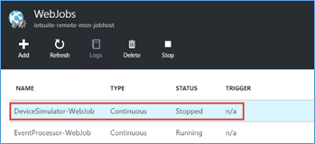
- Click on Settings -> WebJobs.
- Highlight the DeviceSimulator-WebJob and click on Stop.
IoT in Azure is a fun and very exciting space. If you want to learn more about IoT and Azure, check out the learning path available here. Hopefully this post helped to accelerate some of your own learning so you can explore the possibilities of IoT on Microsoft Azure.
Thanks for reading.
Cheers!
Comments powered by Disqus.